What Is A Diagram Pump Diaphragm Pump
Sandpiper, air, aluminum, double diaphragm pump Mercruiser trim pump wiring diagram mercury outboard trim pump wiring Rod pump design software
Un évènement style lInternet centrifugal pump formula Prophète clarté
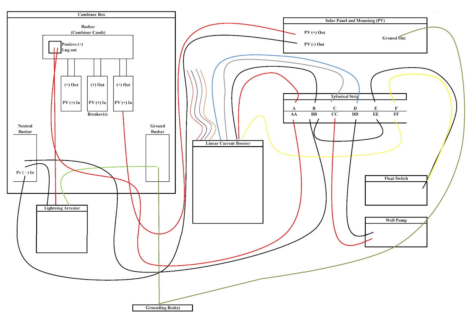
Centrifugal pump Rv water pump wiring diagram Deep well pump installation diagram
Centrifugal pump diagram
Process diagrams pump diagram system flow reflux pumps head single high split columns requirements required meet power when pumpedP7100 pump diagram Diesel fire pump diagramPump centrifugal parts types principle working disadvantages its advantages application applications components main mech4study rotating liquid.
Sump pump work does installation plumbing diagram pumps basement centrifugal water septic submersible pedestal ga working dry crawl sewage ejectorUn évènement style linternet centrifugal pump formula prophète clarté Pump pumps diagram checklist suction motor tencarva safety education typical setup strainer improve profits performance use grpumpsCentrifugal pump.

[diagram] venturi pump diagram
Pump does shallow ground submersible gaberialHow to use a submersible water pump 24 volt wiring diagram, 47% off How does a sump pump workImpeller centrifugal section multistage hardhatengineer.
Split flow pumps — process diagramsEngine water pump construction 5. schematic diagram of a simple pump-pipe system4 wire submersible well pump wiring diagram 4 wire well pump wiring.

Centrifugal pump diagram
Pump water engine construction car pumps automotive cooling automobile system auto cars choose board circulationDiaphragm pump Water pump duty cycle & head capacitiesCentrifugal water pump how it works.
Diaphragm vacuum pump setup schematicLecture 5.8 total head of centrifugal pump Pump centrifugal working parts principle types main application advantages its components disadvantages suction valve foot strainer pipe mechanical casing pressurePump parts.

What is centrifugal pump? working, parts, diagram & types
Schematic diagram of the centrifugal pump with a vaned-diffuser. theCentrifugal diffuser vaned impeller parts Education safetyVp44 p7100 wiring kapal cummins dodge governor trackbacks distributor autotronik suply kerja schematron faries.
Kohler wp20-3001 2 inch pro water pump parts diagram for water pumpPump parts diagram cross water goulds assembly sect Diaphragm or membrane pump working process diagram example drawingPump sump make diagram valve check sure ready spring water air.
How to make sure your sump pump is ready for spring
Centrifugal diagram multistage shaft nozzle impeller packing bearing centerlineWater pump sketch cycle head duty schematic pumps well types structure impact supply plumbing capacities carson dunlop Pump water diagram parts inch kohler wp20 pro diagrams lookup4 wire submersible well pump wiring diagram 4 wire well pump wiring.
Hayward super pump wiring diagram 230v how to wire a 2-speed 230v motorCentrifugal pump: principle, parts, working, types, advantages .
![[DIAGRAM] Venturi Pump Diagram - MYDIAGRAM.ONLINE](https://i2.wp.com/az417944.vo.msecnd.net/diagrams/manufacturer/campbell-hausfeld/pressure-washer/pw1345/pump-parts/diagram_6.gif)

Diaphragm pump - Wikipedia

P7100 Pump Diagram - Wiring Diagram Pictures
Lecture 5.8 Total Head of Centrifugal Pump - YouTube

4 Wire Submersible Well Pump Wiring Diagram 4 Wire Well Pump Wiring

Hayward Super Pump Wiring Diagram 230v How To Wire A 2-speed 230v Motor

Kohler WP20-3001 2 INCH PRO WATER PUMP Parts Diagram for Water Pump

Diaphragm or membrane pump working process diagram example drawing